SMT Pick and Place Nozzle Vacuum Failure Troubleshooting and Maintenance
In modern Surface Mount Technology (SMT) PCB assembly, a pick and place machine vacuum failure is one of the most frequent and disruptive equipment issues. When high-speed placers suddenly fail to pick up components, trigger frequent errors, or cause excessive pick-up drop rates, the entire production line halts.
Whether you are troubleshooting surface mount device (SMD) pick-up errors, optimizing pick and place equipment maintenance, or improving PCB assembly line efficiency, this comprehensive guide covers every root cause, detailed diagnostic step, and preventive maintenance best practice.
I. Comprehensive Overview of SMT Vacuum Failures
Vacuum failure in a pick and place machine occurs when the pneumatic system fails to generate or maintain sufficient negative pressure to lift a component from its feeder pocket. While it often appears to be a simple issue with the nozzle, it typically spans multiple interconnected subsystems:
Nozzle-level anomalies (clogging, wear, or incorrect sizing)
Vacuum system degradation (low pressure, clogged filters, or leaks)
Feeder mechanical errors (misalignment or improper tape feeding)
Software parameter discrepancies (incorrect pick height or dwell times)
Incoming material defects (warped tape or oxidized leads)
II. Detailed Causes and Professional Solutions
1. Nozzle-Level Issues
The nozzle is the primary interface between the machine and the component, operating in harsh conditions with high wear rates.
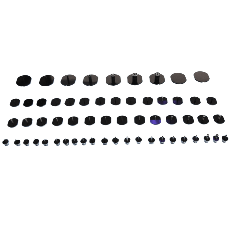
Clogged Nozzles: Dust, solder paste residue, and static-attracted debris block the inner bore, causing a sudden drop in vacuum.
Worn or Damaged Nozzles: Tip wear, micro-cracks, or chipped edges cause air leaks, preventing an airtight seal against the component.
Mismatched Nozzle Sizes: Using an incorrect bore size leads to vacuum loss (e.g., using a large nozzle on ultra-small 0201 or 01005 components).
Solution: Match nozzle dimensions strictly to component specifications (e.g., 0.25–0.35 mm for 0402, 0.18–0.25 mm for 0201, and 0.15–0.18 mm for 01005).
Nozzle Detection Errors: Self-diagnostic failures can cause placement software to auto-disable specific nozzles.
2. Vacuum System Malfunctions
The vacuum system supplies the pneumatic force required for component handling.
Insufficient Vacuum Pressure: Negative pressure dropping below standard operating ranges (-60 kPa to -85 kPa during operation; pick threshold > 53.33 kPa) results in dropped parts.
Solution: Monitor system pressure gauges. If pressure drops significantly (e.g., to -30 kPa), inspect the vacuum generator, pneumatic lines, and filters.
Clogged Vacuum Filters: Saturated filter elements severely restrict airflow and system efficiency.
Damaged or Loose Tubing: Cracked pneumatic lines or loose push-to-connect fittings cause hidden vacuum leaks that are difficult to trace.
Solution: Inspect all air lines for kinks, cracks, or flattening. Apply soapy water to joints to check for bubbling, and replace compromised lines.
Solenoid Valve and Pump Faults: Aging vacuum pumps, worn bearings, or sluggish solenoid valves degrade overall system performance.
3. Feeder and Material Positioning Issues
Feeders position components precisely under the pick and place head.
Feeder Misfeeding: Worn ratchet gears, debris accumulation, or weak springs cause components to stop short of the pickup center.
Solution: Disassemble and clean gear debris, replace worn-out springs, adjust mechanical tension, and perform a positioning calibration.
Improper Feeder Installation: Unlocked feeder stations shift picking coordinates, causing offset grabs.
Tape Loading Errors: Loose carrier tape, overtightened reels, or unpeeled cover films obstruct the pick-up zone.
4. Programming and Parameter Settings
Incorrect Z-Axis Pick Height: Excessive downward pressure pushes components into tape pockets, while insufficient depth fails to establish contact.
Pick Position Offset: Misaligned software coordinates cause off-center grabs, leading to component tipping or shifting.
Inadequate Suction and Dwell Delays: Low suction intensity or insufficient vacuum dwell time causes components to drop mid-transfer.
5. Incoming Material Quality Issues
III. Step-by-Step Troubleshooting Workflow
To resolve pick and place vacuum failures efficiently and minimize line downtime, follow this structured, logical sequence:
Step 1: Check for “False Alarms” — Verify nozzle type matching, inspect for obvious nozzle clogs, check tape status, and confirm feeder placement.
Step 2: Inspect the Vacuum System — Check if system negative pressure meets standards ($\ge$ -60 kPa), inspect filters, and verify line integrity.
Step 3: Service Nozzles — Clean blocked nozzles, ultrasonic wash with alcohol, or replace worn tips.
Step 4: Maintain Feeders — Clear debris from feeders, replace worn springs, and run station calibrations.
Step 5: Adjust Software Parameters — Fine-tune Z-axis pick heights, pickup coordinates, and vacuum dwell times.
Step 6: Evaluate Material Quality — Inspect component lead condition, packaging dimensions, and tape tension.
IV. Preventive Maintenance Best Practices for SMT Lines
Nozzle Care: Daily cleaning before shift end; weekly ultrasonic alcohol baths to keep internal bores clear.
Vacuum System Upkeep: Weekly cleanliness audits, monthly pump performance checks, and semi-annual vacuum filter replacements.
Feeder Lifecycle Management: Routine mechanical inspections and proactive replacement of worn feeders.
Environmental Control: Maintain workshop ambient humidity between 40% and 60% to prevent static charge buildup and airborne dust accumulation.
Data Monitoring: Real-time tracking of vacuum negative pressure levels, ensuring component pick/throw loss rates stay below 0.3%.
V. Conclusion: A Systematic Approach to SMT Vacuum Failures
In SMT manufacturing, resolving a pick and place nozzle vacuum failure goes far beyond simply swapping out a worn tip. Because issues can originate anywhere from the central vacuum pump to individual feeder mechanics and software coordinates, technicians must approach troubleshooting with a structured, logical mindset.
Always follow this proven diagnostic hierarchy:
False Alarm Confirmation (Basic checks on setup and tape status)
Nozzle Inspection (Cleaning or replacing worn tips)
Vacuum System Verification (Checking pressure gauges $\ge$ -60 kPa, lines, and filters)
Feeder Maintenance (Clearing debris and running position calibrations)
Parameter Fine-Tuning (Adjusting Z-axis pick height and dwell times)
Incoming Material Quality Audit (Evaluating component packaging and tape integrity)
By adhering to this step-by-step diagnostic path, floor operators can rapidly identify root causes, minimize production downtime, and ensure peak PCB assembly line efficiency.