Deep Dive into SMT Pick and Place Machine Component Rejection (Waste/Throwing) Causes and Systematic Troubleshooting
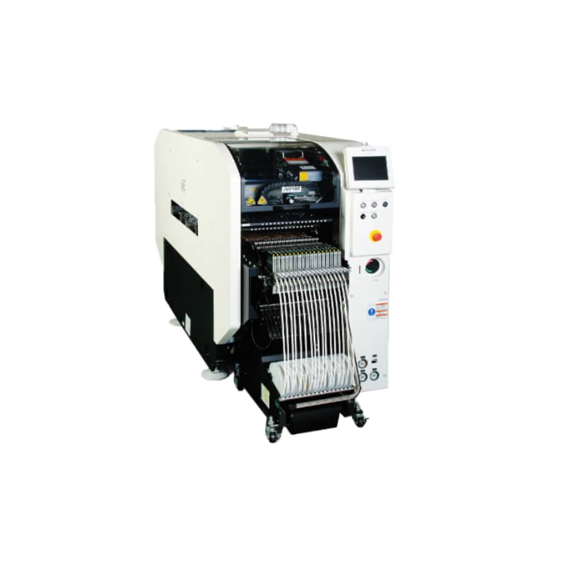
In SMT (Surface Mount Technology) manufacturing, component rejection—commonly known as “throwing parts” or “dropping”—is an unavoidable challenge for every production line. Rejection occurs when the pick-and-place machine fails to mount a component onto the designated PCB coordinate and instead discards it into the waste bin, or fails to pick up the component altogether before executing a rejection cycle.
Rejections not only cause direct material losses but also extend production time, reduce line efficiency (OEE), and drive up manufacturing costs. When rejection rates remain chronically high, the waste of expensive microchips and delivery delays simultaneously erode corporate profit margins and brand reputation.
This guide provides a systematic, SEO-optimized breakdown of the root causes and diagnostic pathways for SMT placement machine rejections across seven core dimensions: feeders, nozzles, vision recognition systems, vacuum systems, program parameters, incoming material quality, and environmental/operational factors.
I. Definition and Grading of Rejection Rates
Rejection Rate=(Number of Rejections/Total Pickups)×100%
The industry benchmark target is below 0.3%. Standards vary depending on component categories:
Class A Components (Chips/ICs): Target zero rejections.
Class B Components (Diodes, Crystals, etc.): Controlled below 0.1%.
Class C Components (Chip Resistors/Capacitors): Controlled below 0.3%.
Rejection Rate Warning Tiers:
Target Level: Below 0.1% (for 0603 and larger) or below 0.2% (for precision components like 0201/01005).
Warning Threshold: Exceeding 0.3% requires immediate troubleshooting.
Line-Stop Threshold: Exceeding 0.5% requires immediate production suspension for corrective maintenance.
Note: Under optimal machine maintenance, rejection rates can be stably controlled around 0.05%.
When the rejection rate crosses the 0.3% warning line, it ceases to be an isolated incident and becomes a production crisis requiring systematic resolution.
II. Feeder Issues: The Primary Culprit (Approx. 40% of Rejections)
Inadequate feeder precision is the single largest cause of rejections, accounting for roughly 40% of occurrences.
The primary function of a feeder is to deliver components punctually and accurately to the nozzle pick-up position. Common mechanical failures include:
Pick-up Center Offset: The most common precision issue. When feeder positions warp or feeding fails, nozzles miss the component center, causing components to tilt, flip, or offset. For precision components like 0201, even a 0.05mm deviation triggers pick-up errors.
Inaccurate Feeding Pitch: Damaged ratchet wheels or tape sprocket misalignments cause components to skip or jam in slots. Foreign debris underneath feeders, fatigued springs, or electrical faults also lead to pick-up failures.
Improper Cover Tape Pressure: Insufficient pressure causes components to bounce out of pockets, while excessive pressure crushes them.
Troubleshooting and Corrective Actions:
Use a feeder calibration station or built-in calibration software to measure pick-up offsets, applying electronic compensation or mechanical adjustments to keep deviations within ±0.05mm.
Test feeding pitch using sample tapes; deviations exceeding ±0.05mm require gear or motor parameter adjustments.
Inspect cover tape pressure springs, maintaining normal operational force between 0.5 and 1.5N.
Preventative Maintenance: Establish a quarterly calibration schedule. For electric feeders, precision should be maintained within ±0.03mm.
III. Nozzle Issues: The Most Frequent Operational Fault (Approx. 20% of Rejections)
Nozzle-related rejections account for approximately 20% of issues. Because nozzles make direct contact with components in a harsh production environment, they wear out rapidly.
Nozzle Clogging: Solder paste residue, dust, or electrostatic debris block internal nozzle holes, dropping vacuum levels and suction force. Blocked nozzles cause components to tilt or drop mid-transit.
Nozzle Wear: Worn or cracked tips cause vacuum leaks and insufficient pressure, eventually preventing airtight seals.
Incompatible Nozzle Selection: Inner diameters that are too small lack suction, while oversized diameters cause fatal vacuum leakage. Proper matching is essential:
01005 components: 0.15 to 0.18mm ceramic nozzles.
0201 components: 0.18 to 0.25mm ceramic nozzles.
0402 components: 0.25 to 0.35mm metal nozzles.
0603 and larger: 0.5 to 0.8mm metal nozzles.
Troubleshooting and Corrective Actions:
Execute automated nozzle cleaning programs (vacuum plus blow-off pulses) every shift.
Perform weekly ultrasonic baths with isopropyl alcohol (40kHz for 10 minutes) and verify internal bore clarity.
Maintain vacuum pressure above −85kPa; clean or replace nozzles if thresholds drop.
Track nozzle usage cycles via the MES (Manufacturing Execution System) to trigger automated replacement warnings.
IV. Vision Recognition System Issues: When the Machine Cannot “See” Components
The vision system acts as the “eyes” of the placement machine. When visibility fails, rejections follow.
Lens Contamination: Dust or debris on camera or laser lenses disrupts image processing.
Incorrect Lighting Parameters: Inappropriate lighting intensity, poor contrast, unclear component markings, or abnormal reflectivity cause cameras to reject components.
Excessively Strict Recognition Tolerances: Overly rigid algorithm models in component libraries cause normal parts with micro-variations to be misidentified as defects.
Troubleshooting and Corrective Actions:
Clean vision system surfaces regularly to keep camera lenses spotless.
Tune lighting intensity, grayscale, contrast, brightness, and edge tolerances.
Relax recognition tolerances (position ±0.05mm, angle ±3∘) to accommodate minor component variations. Upgrade to high-resolution cameras for advanced precision.
V. Vacuum System Issues: Suction Failures and Mid-Air Drops
The vacuum system provides the pneumatic power required to “pick, transport, and place” components.
Insufficient Air Pressure: Blocked pneumatic channels, restricted airflow, or vacuum leaks drop system pressure, causing parts to drop during transit.
Vacuum Line Leaks: Damaged tubes or loose fittings cause gradual vacuum degradation, which is often difficult to isolate.
Troubleshooting and Corrective Actions:
Adjust main air pressure to equipment specifications (typically 0.5 to 0.6MPa).
Clean pneumatic lines and repair leaks immediately.
Ensure vacuum levels do not fall below −60kPa.
VI. Program and Parameter Configuration Errors: Software-Level Pitfalls
Machine operations rely entirely on programming instructions. Even flawless hardware will fail if parameters are misconfigured.
Incorrect Component Parameters: Mismatches between programmed dimensions (length, thickness, brightness) and actual incoming parts cause recognition failures. For instance, component thickness errors exceeding 0.05mm disrupt pick-up height calculations.
Improper Pick-up Coordinates and Heights: Incorrect pick-up positioning or Z-axis descent depth (standard rule: contact component plus 0.05mm downward overtravel) causes offsets or unstable pickups.
Troubleshooting and Corrective Actions:
Verify physical dimensions using digital calipers and update the machine component library.
Fine-tune Z-axis pick-up depths and compensation offsets. Conduct first-article inspections (FAI) for every new production batch.
VII. Incoming Material Quality: Root-Cause Vulnerabilities
Incoming material flaws represent the hardest rejection variables to resolve solely through equipment adjustments.
Component Defects: Irregular dimensions, oxidized terminations, contamination, or physical damage—typically manifesting across entire supplier lots.
Packaging Issues: Moisture absorption causing carrier tape warping, uneven cover tape peel strength (electrostatic adhesion), or non-standard bulk packaging.
Troubleshooting and Corrective Actions:
Enforce strict Incoming Quality Control (IQC) inspections and communicate issues immediately with suppliers.
Bake moisture-sensitive components before reloading into production tapes. Prioritize Tier-1 component suppliers compliant with automation standards.
VIII. Environmental and Operational Factors: Overlooked Variables
Environmental Conditions: Excessive workshop temperatures or low humidity generate static electricity and dust. Inadequate facility sealing accelerates machine contamination.
Operator Error: Improper feeder loading, failure to clear waste tape promptly, or manual data entry mistakes amplify across high-speed runs.
IX. Conclusion: Systematic Troubleshooting is the Only Path to Lower Rejection Rates
Controlling SMT rejection rates is never solved by simply swapping a nozzle or tweaking a single parameter. Reducing throw rates from 0.5% down to 0.1% requires synchronized optimization across feeder calibration, nozzle maintenance, component parameter accuracy, vision tuning, and pneumatic integrity.
Recommended Troubleshooting Priority:
Feeder Calibration (∼40% of root causes)
Nozzle Matching and Cleaning (∼20% root causes)
Component Parameter Correction (∼15% root causes)
Vision System Optimization (∼10% root causes)
Vacuum System Checks (∼10% root causes)
Best Practices for Preventative Control:
Establish quarterly feeder calibration protocols.
Track nozzle lifecycles through MES automated alerts.
Perform rigorous first-piece inspections (FPI) for every new material lot.
Maintain strict environmental temperature/humidity controls alongside comprehensive ESD and dust mitigation.
Ultimately, low rejection rates reflect both operational excellence and engineering mastery, safeguarding production uptime, delivery schedules, and customer trust./